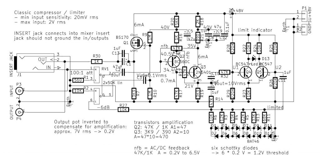
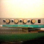
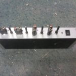
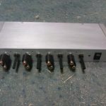
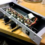
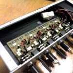
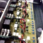
It happens that experimental approaches have victims. These are amplifiers and especially loudspeakers. Two amplifiers and a couple of loudspeakers of Cirkulacija 2 are now dead. What was needed is an effective audio compressor/ limiter. This is it. After recent changes seems to work well.
The nature of limiter is that it instantly changes the amplification factor – the moment the input peak signal surpasses a certain voltage level – all the sound is than pushed down at the output. This produces a pumping effect on the lower level sounds in complex sound waveform – however, the overall level is instantly back to normal – after the peak is over. This pumping is not to be mixed up with the pumping of a compressor – which uses attack and release time relaxation principle. The progressive limiting that staggers the amplification factors in multiple stages overcomes somewhat the idea of simple sound limiting.
Background:
The basic principle I used is something called The Nachbaur Diode Limiter found here (http://prairieboxes.blogspot.com) that points to Fred Nachbaur’s Dogzilla Guitar Amplifier- and especially the limiter. It is a relatively modern day tube design. I had the intention to build a tube compressor some day, but maybe now i will not. This limiter has a progressive attenuating effect depending of the signal level, so it does not miss the transients. I decided on six stages of progressive peak attenuation.
I also decided to use discrete transistor design, hopefully finding one discrete transistor preamplifier schematics by Jean Hiraga (powered by 200V) – that i remember from the old times. But no luck, so I settled for a two transistor amplifier design – with enough local feedback. The power supply is a 48V switching mode block that i happen to have had – it gives enough of dynamic headroom. For now i use a pi filter to bring down the remains of high frequency still visible on the oscilloscope.
The configuration is simple:
– input/output stereo jack is compatible with the insert connectors on most mixing desks. Otherwise the stereo cinch to jack adapters are used. Recently I added the input / output cinch pairs at the back;
– potentiometer is double – one at the input and one at the output – but in reversed/ complementary action: input signal is attenuated by the input potentiometer to get the signal to some predefined low level (0.1Vrms) level – then gets amplified by a factor of around 30 – to get to some 3Vrms – and attenuated at the output in reverse proportion – to come back to about the original level. The maximum input voltage of the signal is about 3V~ (4V peak to peak). In such case the attenuation at the input pot is maximum / and no attenuation at the output pot.
– a LED indicator is the visual information of the level of limiting effect – it should just visibly blink on normal sound levels. If it lights constantly the input level is set too high – the potentiometer should be turned down.
The unit has been tested and after some adaptations of resistor values it seems very good indeed. It should now go into “saving the loudspeakers” business.
Circuit:
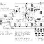
– Q1 is the output source follower (BS170 mosfet) – buffering the output from the output part of double potentiometer and the diode limiter divider
– Q2 (BC560) and Q3 (2N4501) is a two stage amplifier with local and global feedbacks applied
– Q4 and Q5 is a differential pair comparator
– R14 is the first part of voltage divider
– diodes D1 to D12 are schottky diodes that form the passive – level-dependent – second part of voltage divider with staggered resistor values for progressive level-dependent voltage division.
